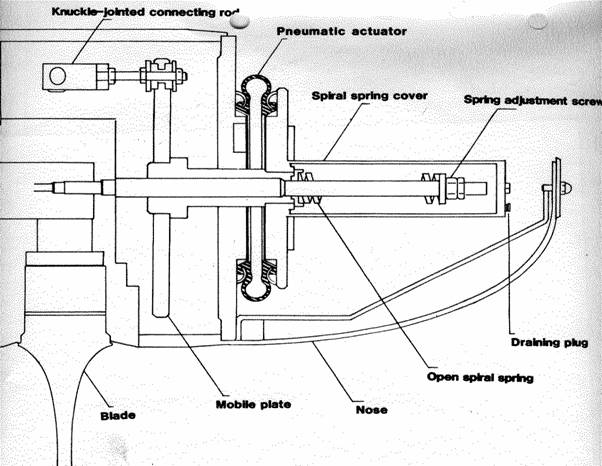
Lets look at this great drawing that was preserved by a previous owner from French River Land Company. It depicts a cut-away view of the runner (propellor). Theres a outer sheet meal nosecone, we dont seem to have that. Inside that is another nose cone that has a big o-ring and sorta seals the innerds from the outers, we got that. Then there is some sort of sheet metal tube that holds the oil and this what I call the jesus bolt and a spring. This Jesus bolt threads into the end of the output shaft from the generator, and holds the runner onto the shaft. The spring and threaded section is the mechanism in which when you lose the grid or there is a fault the oil pressure drops and that spring spring returns the prop blades flat to stop it from overspeeding. This is critical and can prevent overspeed failures. Like without this part the variable pitch mechanism wouldnt work, this part is so quintessential that it would be devestating if it were lost. Yea.... its gone, and not only one is gone but all three seem to be missing. Either I am real dumb or they were all broken, insert problem here. But one end is a m30x.5 thread, and on the other probably some relatively fine thread of a unknown size, and many steps and features inbetween. I know its missing or broken as well because there is no sign of that sheet metal cover for it. I thought I had missed the part in a giant pile of parts from three turbines, so I made a special trip up to the dam just to look for it and didnt see it. So we need to regroup and figure out what we are gonna do.....
Keep Moving Forward
Posted on: August 21st, 2025
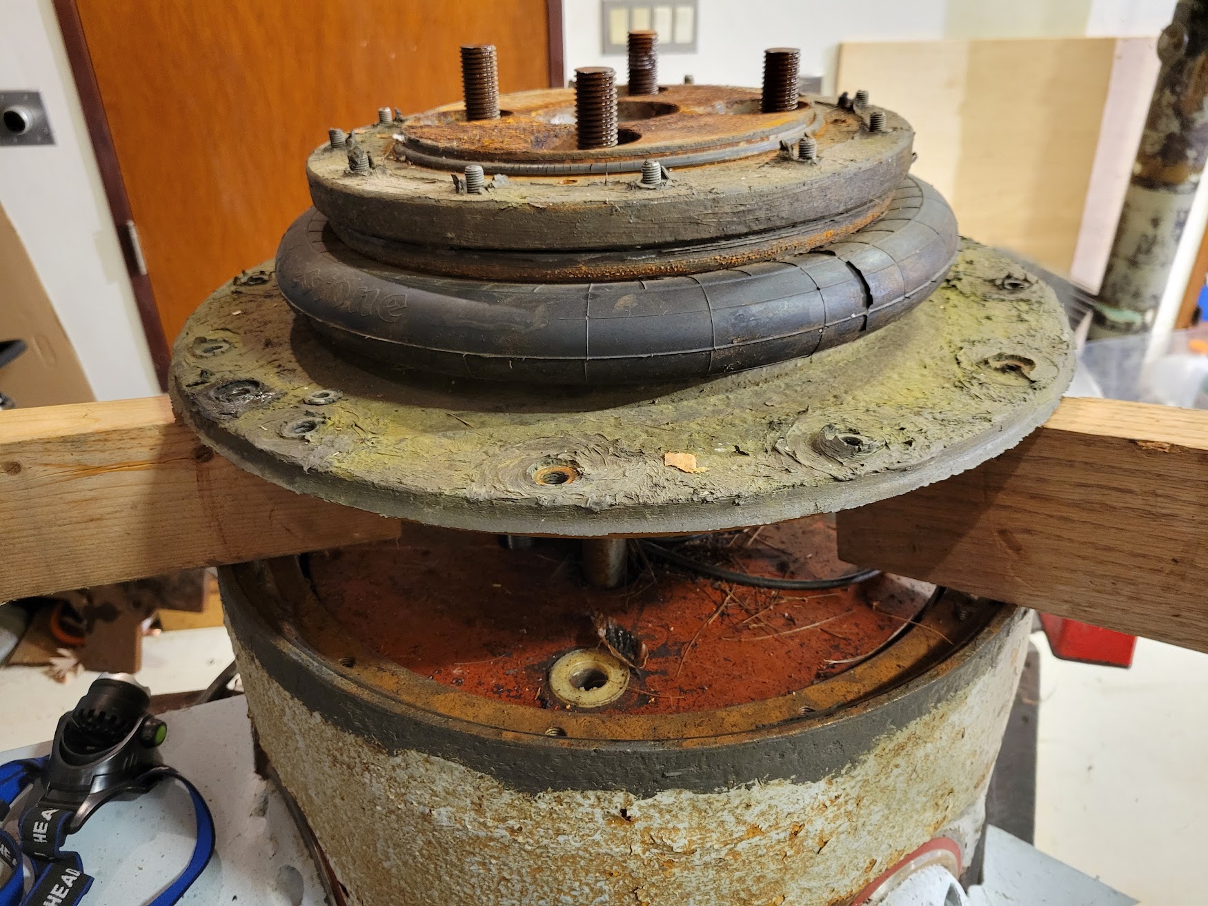
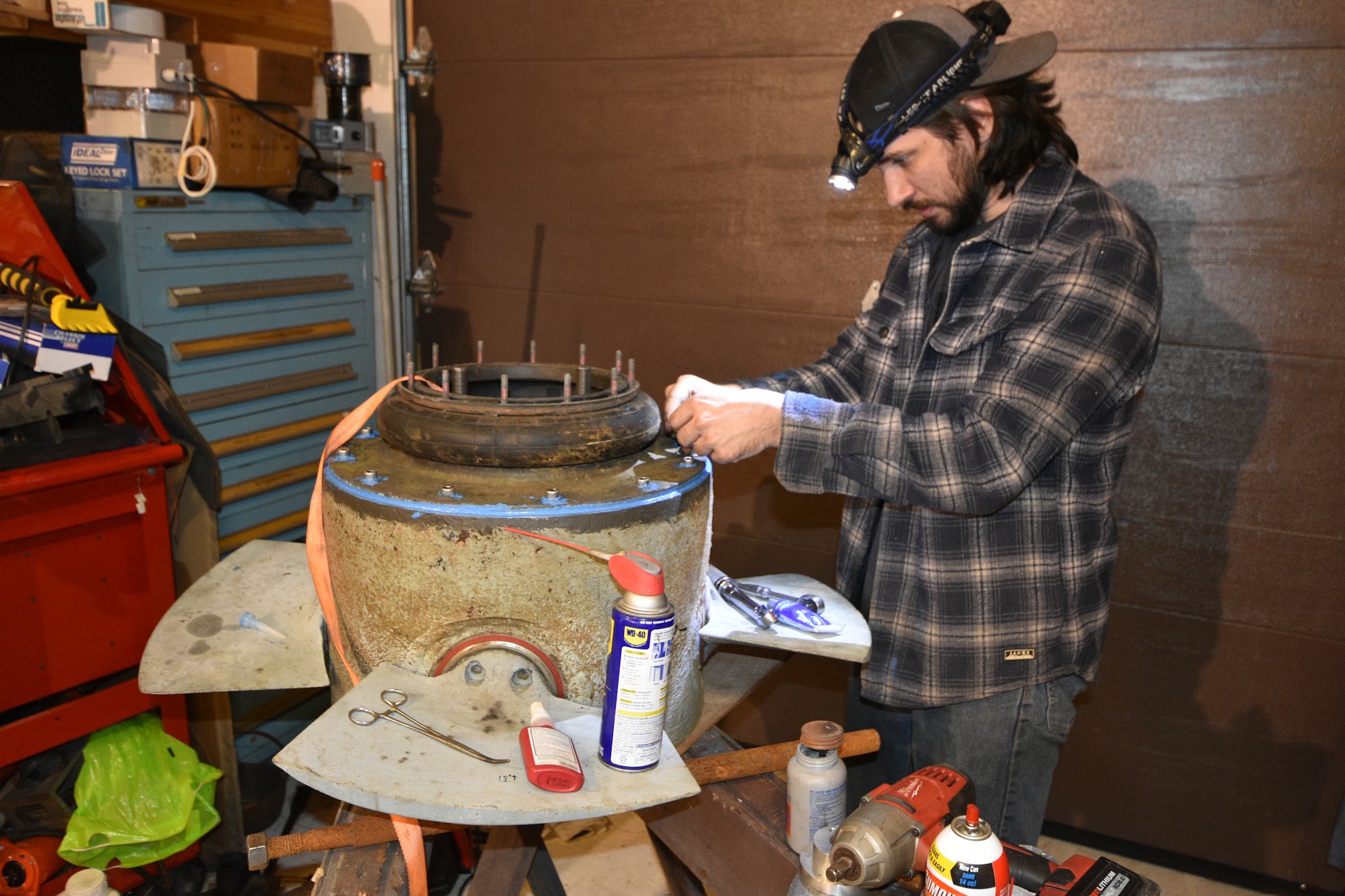
Lets start taking this thing apart to see whats going on inside. Crack open the outmost bolts and just openerup right? Yea no.... This stop little section alone weighs an easy 60lbs, each of those plates are solid half inch steel, and it was slightly recessed in the housing and glued in. So we slowly worked it up with small screwdrivers then bigger ones going all the way around, then small pieces of wood then larger ones. The top set of studs you see is the compression plate to hold the Firestone truck airbag sealed to the assembly.
We get our first peek inside the first layer here, and nasty grimy crap.
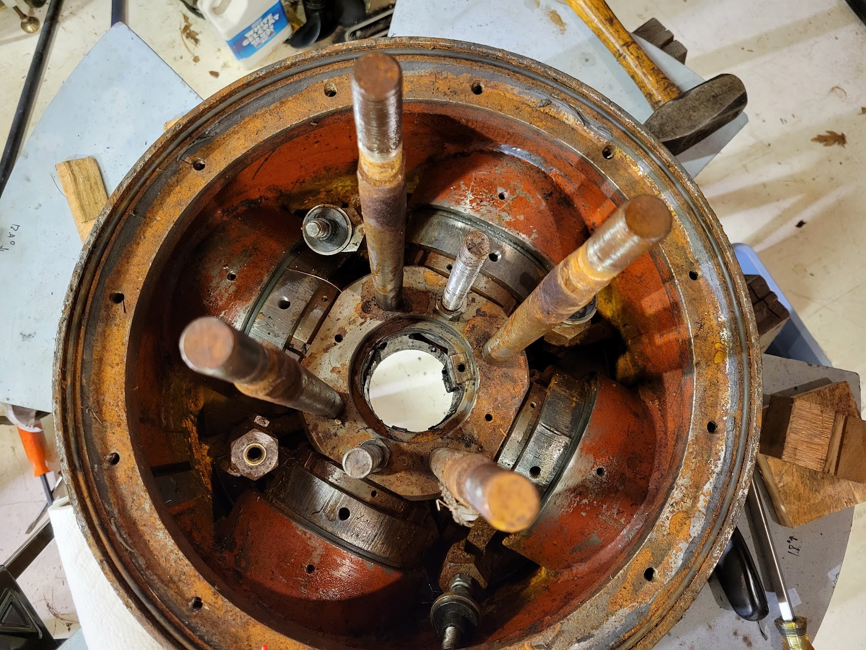
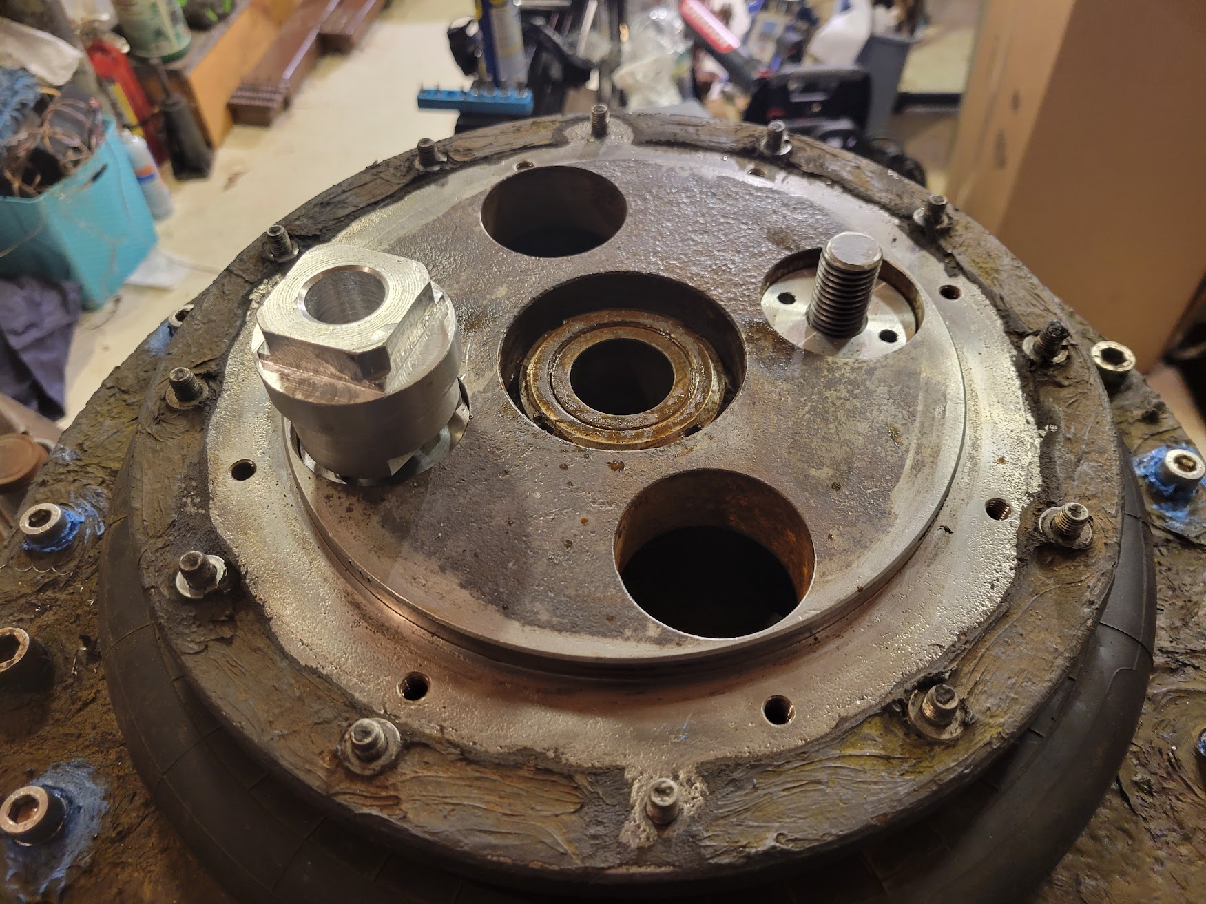
Now that we got that plate out we can sorta see whats going on here. There are the 4 propellor blades that have big seals that are also bushing bearing things. They have special sleeves that I was not going to take apart, we deemed them good. Honestly we really dont know whats going on with these bolts and stuff but some of them are used for jacking the propellor on and off. Its kinda rusty in there and dirty, So I eventually took it outside and pressure washed it out and wow, I don't know of many other times in my life ive been that dirty but yea, it was nasty orange crap coming out.
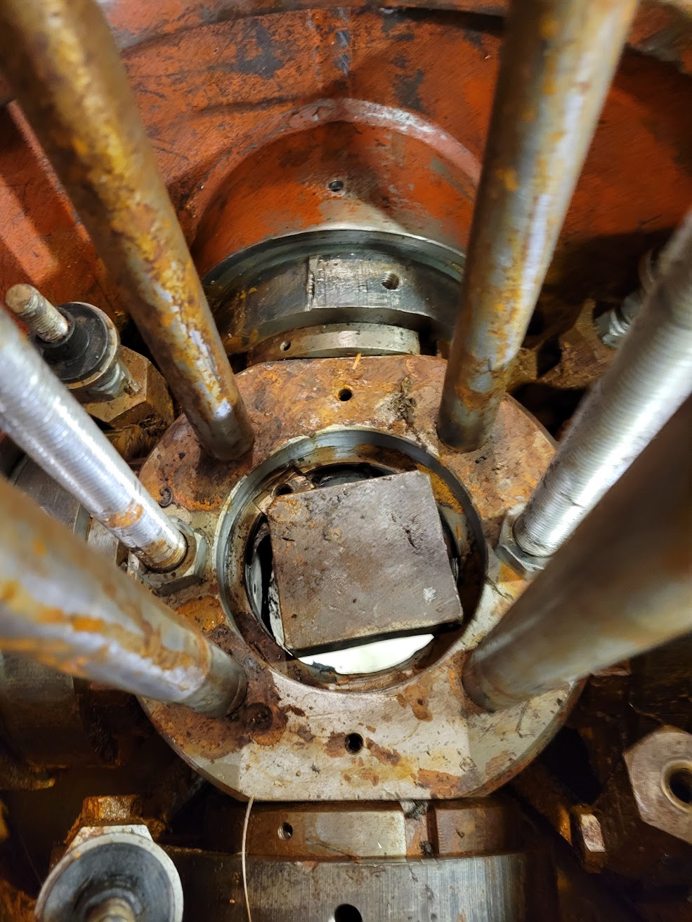
A bonus which was fun, this 1'' thick piece of steel was used to jack the generator off of the runner, it was here for picture purposes only, I had to convince it out the bottom, and lets just say it was a very snug fit in the bore, that later had to be ground smooth.
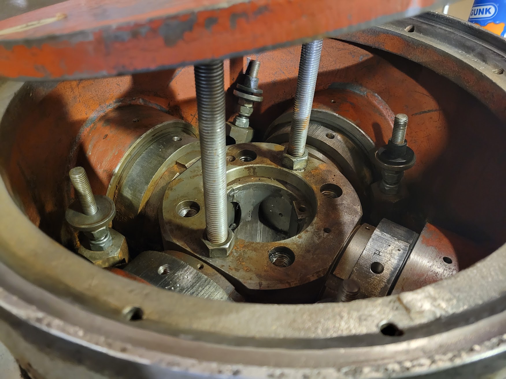
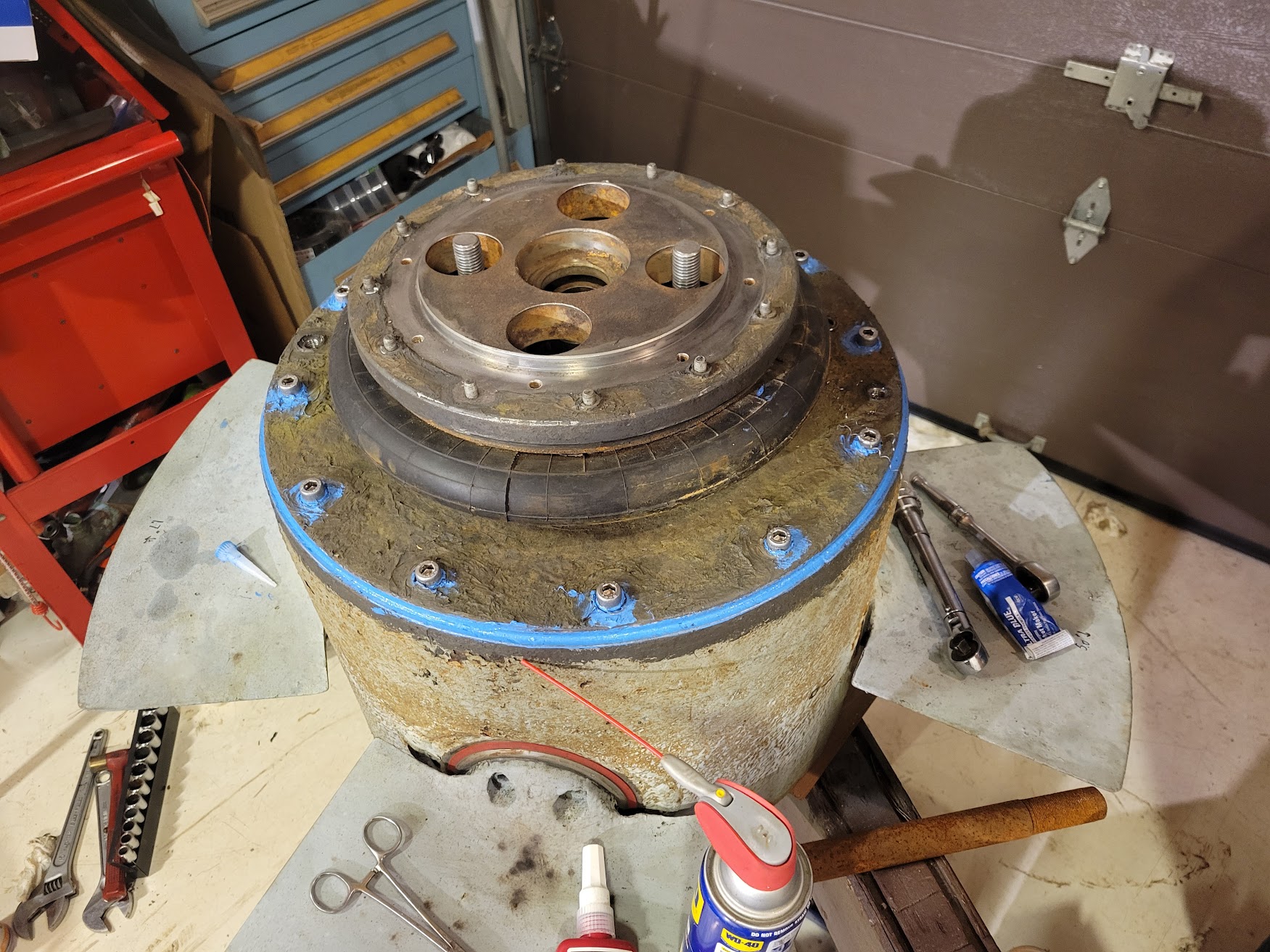
Ok its all cleaned up and coming back together. You can see there are four pivot arms that push and pull the blades of the propellor. The flat setting of the prop is determined by the two nuts below the big washer with the black plastic insert. Why the black plastic insert you ask? Oh maybe because its a single pivot at about a 5'' diameter, and the pivot doesnt go up and down in a straight line, it moves in a arc, so when you bolt the next plate on the plastic has enough to allow this slop, pretty janky but it works. One of these studs came out, and we did'nt know how to put it back in the right place, so I measured the other ones, and made them all the same distance from the face of the pivot body and determined that it was good enough. You will see for our purposes it doesnt matter where they are set, they just matter if they are all sorta the same.
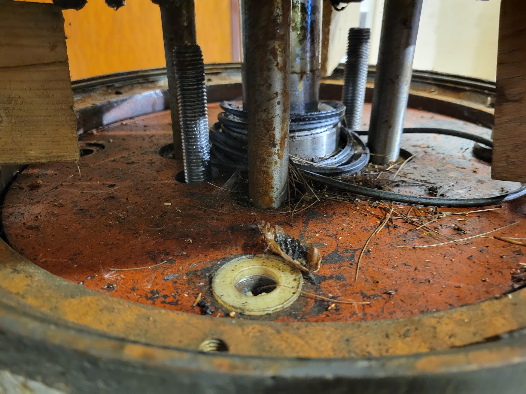
Here is the next layer of the onion. You can see plastic bushing sort of washer things thats where the pivot arms come through and get nutted, again theres enough give in the plastic that a single pivot is fine, sorta. One was missing so I had to make a new one out of delrin. Now this plate sorta floats right now, but you can see that ground shaft coming out of it with washers, this shaft has a oil bushing on the next piece, to keep this one concentiric.
You are thinking to yourself, Aaron how do you get those studs from the pivots below into this plate? There isnt enough from your hand above or blow to do this operation. So what I did was basically balance these studs vertically, and there was enough sticktion that they sorta stayed in place. Then carefully lowered this plate on and made sure none of them fell over. Then carefully lifted one quadrant at a time and with a magnet guided the stud into the hole. I think this only took one or two attempts but it worked well.
With all four in place, with washers and everything and new nylock nuts, everything is looking nice.
Here is the next part going back on, all the faces cleaned and some blue gasket maker applied in a thin layer. This stuff is great, and when applied correctly it works very well but don't go overboard. If I remember correctly there was also a oring here and we ordered o-ring stock and made up some new ones, as well as the gasket maker.
Cleaning up this top plate is pretty satisfying, you can see bolts that are glued in to the truck airbag so they don't leak oil out, a very nice design.....
You can see that plate now almost mounted to its home. Looking promising.
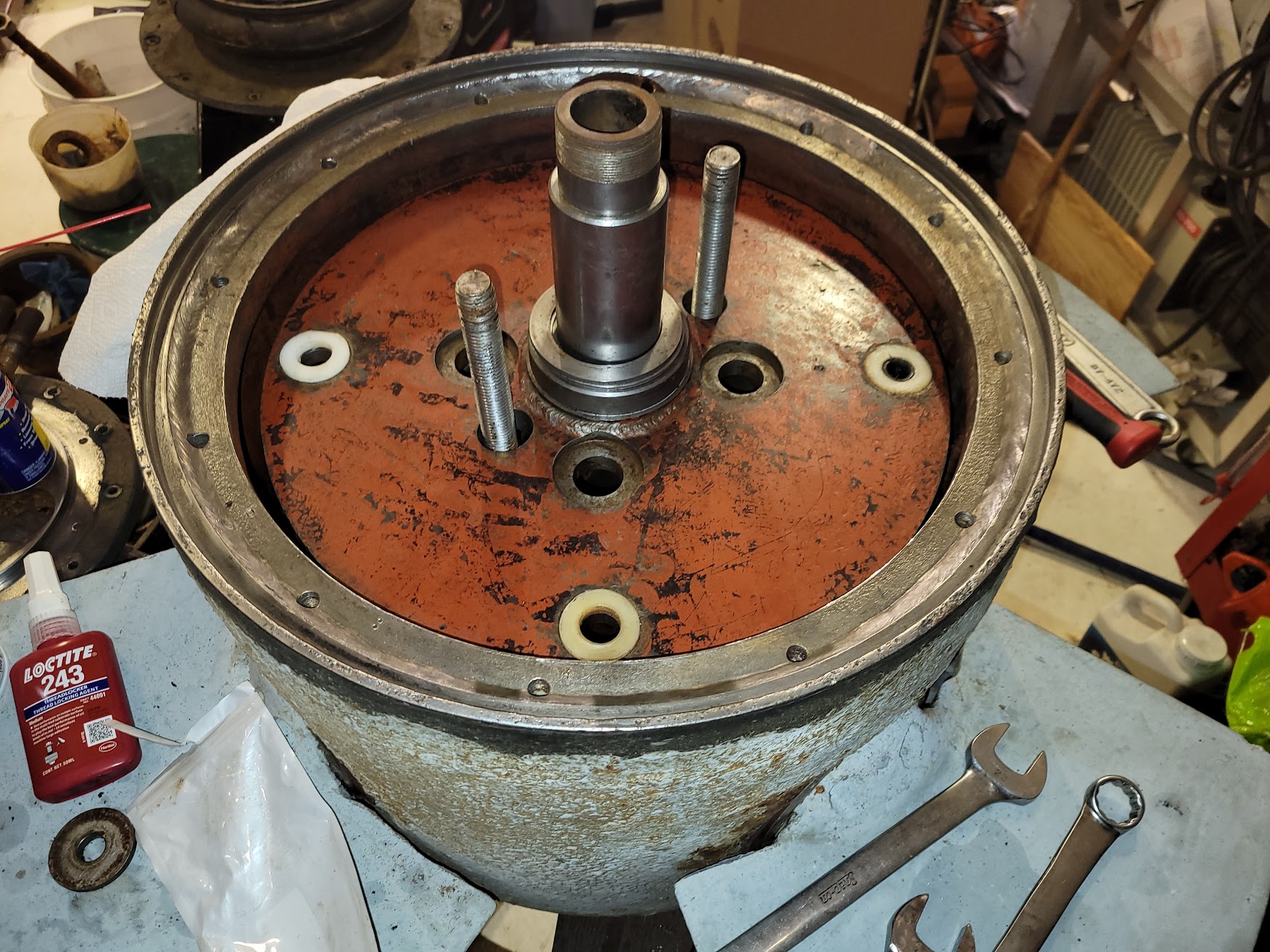
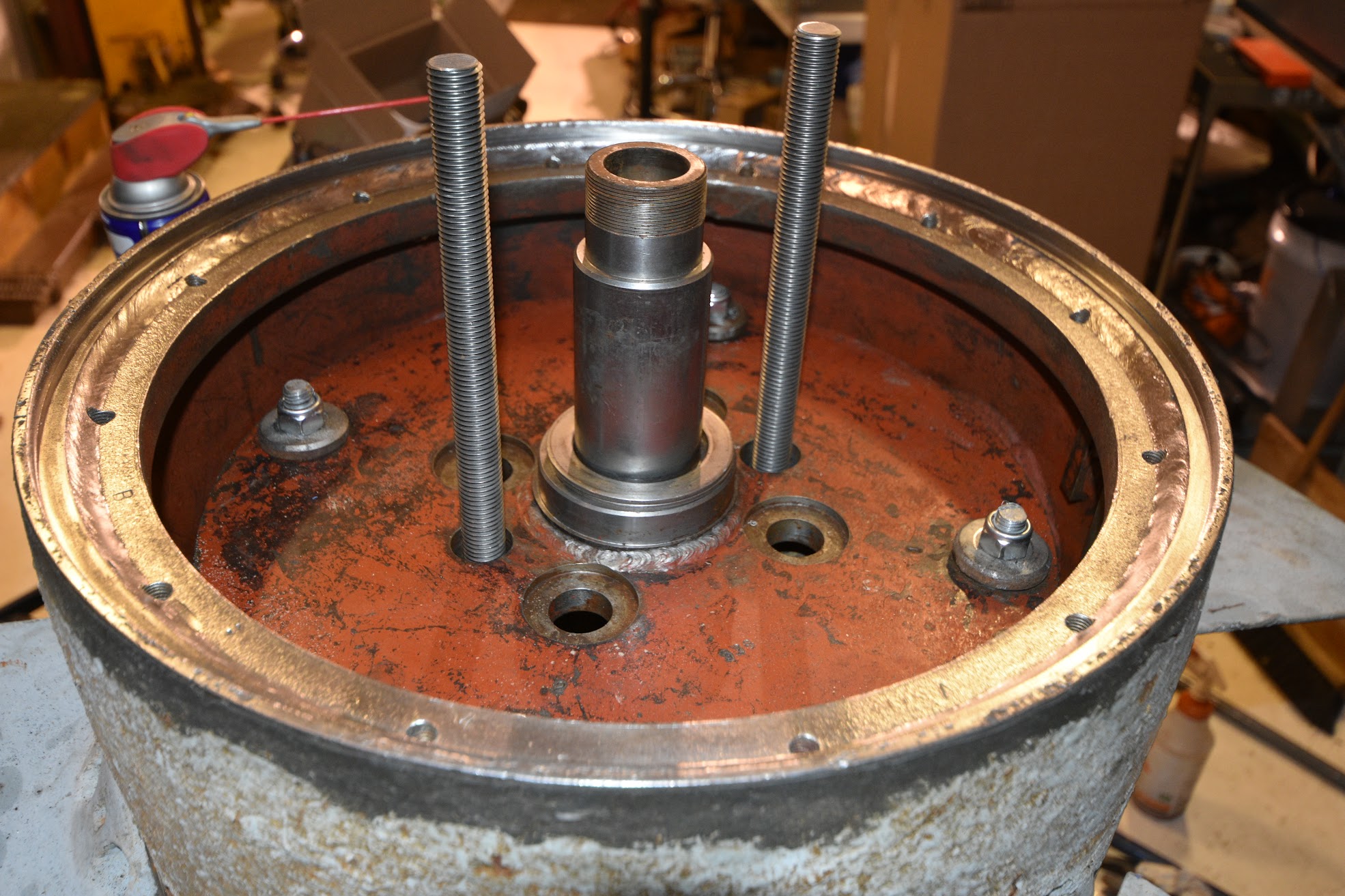
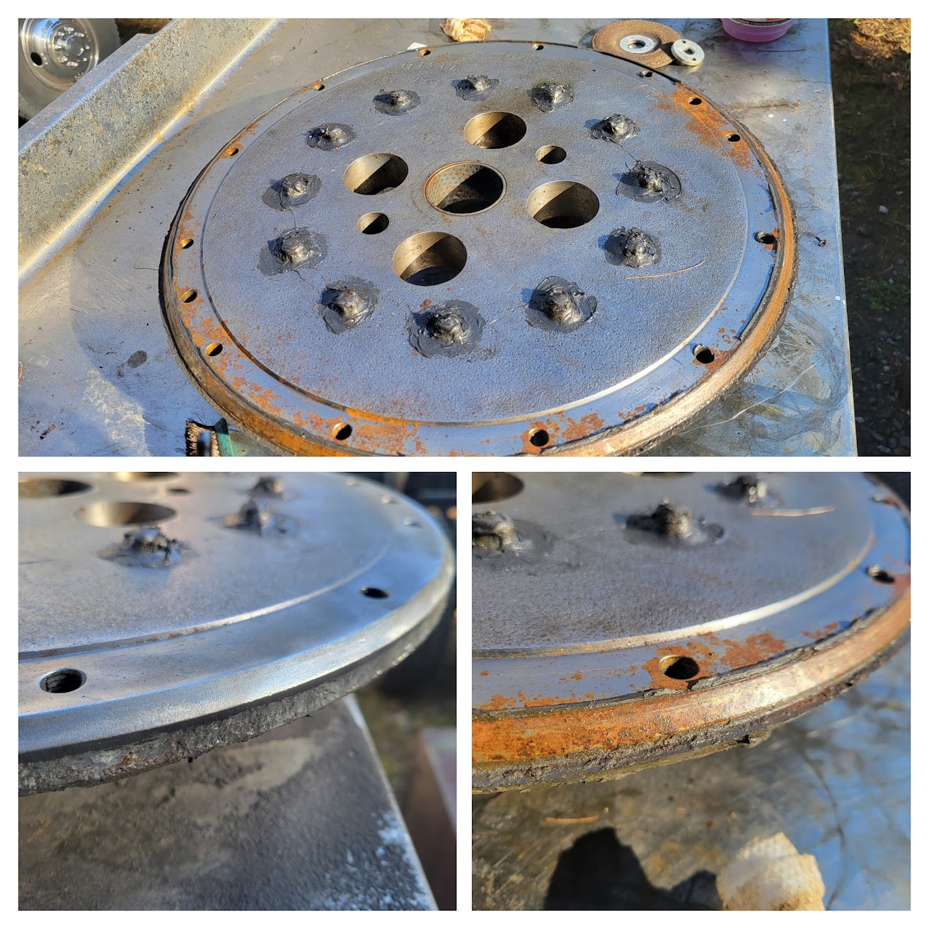
Now here is the fun. Remember how the jesus bolt is gone? Well Aaron what are you going to do, how are you going to control the pitch, or how are you going to keep the blades in one place. You can see in the middle of this image there is a largeish threaded nut that went on the end of that ground shaft that is attached to the plate, that is attached to the pivot arms, that is attached to the prop blades. Ok are you with me so far? So the truck airbag is filled with pressurized oil, the more or less pressure, the more this top plate moves up or down, which in turn pulls up and down on the previous plate which in turn pulls those linkage arms, which in turn move the blades. Well we dont have the critical parts needed to do this anymore, ok so you can see in this process some large threaded rods that are used as jacking screws, they get threaded into blind holes down near where the shaft gets pushed in. Those have now been loctited in and we are using them to constrain the up and down movement of this plate. I made special stepped but nuts essentially had a flange that keeps this plate in place in any position you want. Well Aaron, how are you gonna move the position of the blades to the angle you want? Ah well you can see on the right the special aluminum nut has two holes in it for dowel pins. And on the left is a tool I made, it slips over the threaded rod and has two dowels that go into my special nut. Then jam nuts go on top of my special ones and bingo bongo we have a fixed pitch runner.
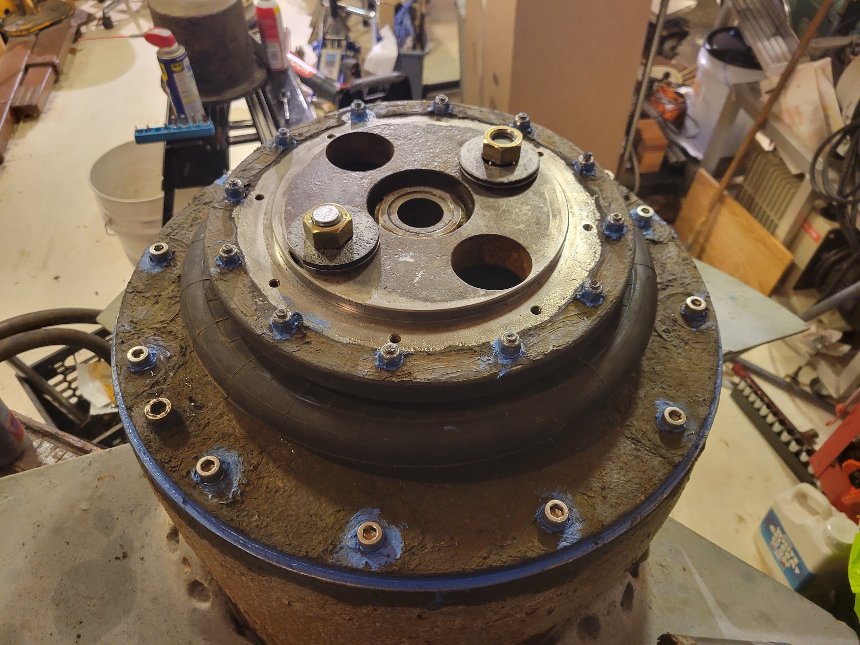
Now you can see it basically done. Oh and a bonus the washers had to have a slight flat on one side or the nose cone wouldnt fit on.... Devil is in the details. we couldnt put the nosecone on quite yet because you need to reach through the center to use the generator output shaft as a puller to help pull the runner onto the girthy shaft.
Here is a sneak peak of everything together, did it go smoothly? Hell fricken no, but it got done. Again Click for some satifying audio.